|
Advertisement / Annons: |
3D CAD drawing:
|
Contents:
Note: |
3, 3D-print of Power terminal box:Info:After finished the drawing I exported it as a TSL file to the slicer software. No error message so I could start to 3D-print it direct after it had been sliced. An 8 hours work. 30% fill factor: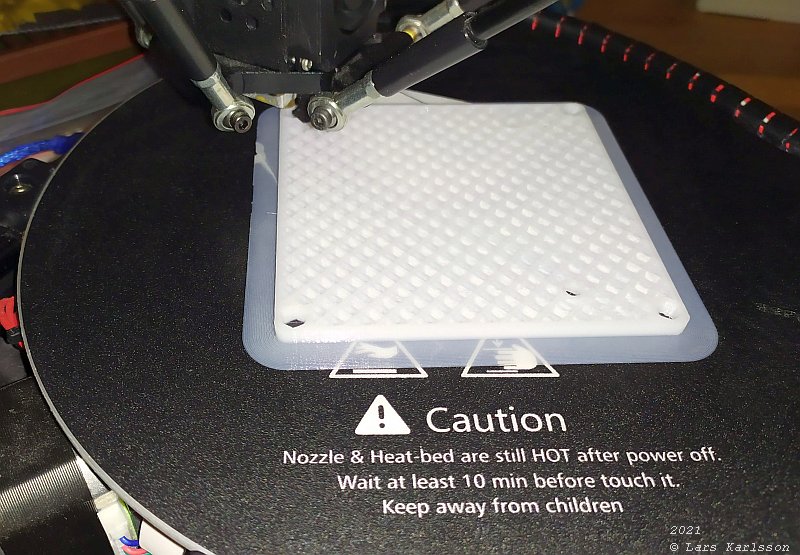
The hollow pattern inside the walls of the box. This time I lowered the infill factor to 30%, I also reduced the wall thickness to 1.5 mm, maybe too thin. 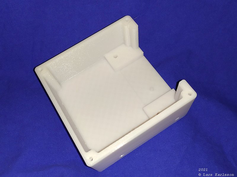
Inspection of the box, not any big mistake what I can see. I had to drill the M3 holes to 3.2 mm, next time I will set the diameter to 3.6 mm. I thread the two M6 holes, I haven't succeed to make the threads direct in the printer yet, but I think that M6 is a bit too small to get a good result. Installing the ground terminal: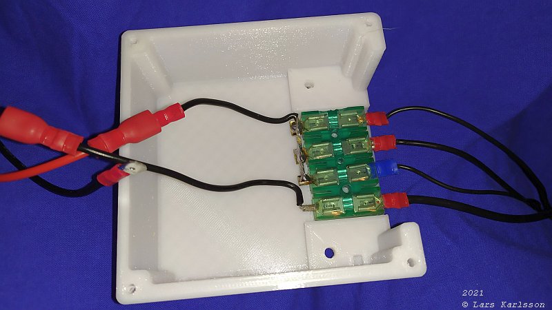
The ground terminal slide in perfect, the two small pillars also fit, but not very strong because of its small size. I broke one immediately. Later I must insulate the wires and terminals outlets. Fuse terminal: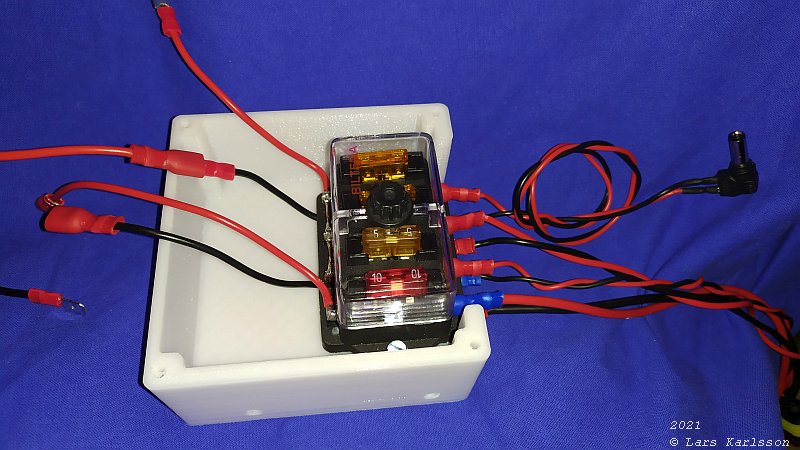
Installing the fuse terminal on top of the ground terminal. It clamp it in place with the two M4 screws. 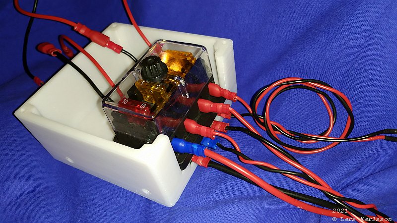
The lower cable is the input 13.7 Volt power. The second an extra low ampere outlet, third main power to the mount and cameras, fourth is the power to the mini PC. With all cables connected with flat connecters it's very easy to do changes in the setup, and I do it often. The power cables are twisted pairs to reduce the electric noise from them, the in coming cable has an area of 2.52 mm to let the voltage drop be low. 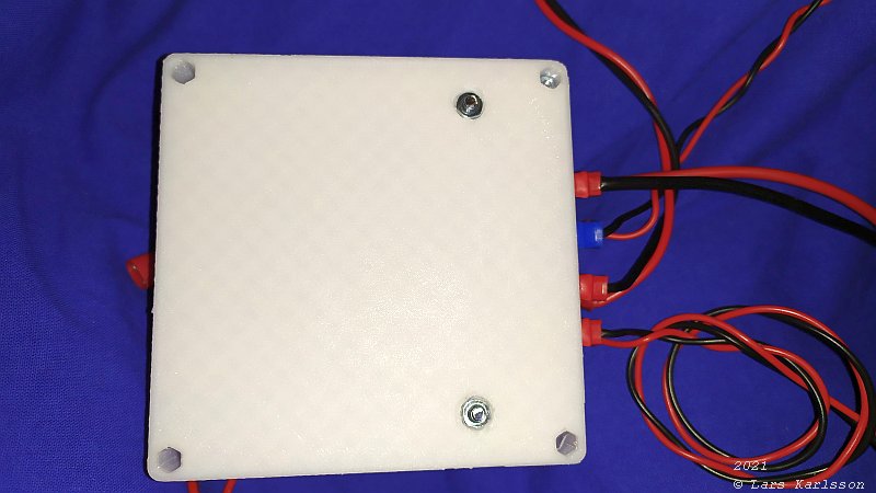
Backside, the M3 nut pockets fit correctly, but the M4 nut pockets were too small, had to drill them up with a 8 mm bore. Later I turned it around and let the screw head be on this side. When pressing the nuts into the pocket, use a long screw to pull the nut into its place, especially the deep M3 pocket can be difficult. Tomorrow I will do the lid to the box, the lid holds the Volt and Ampere meter and the main switch. Later I will draw a L-bracket that connect this box to the mini PC. If I change the PC I only have to do a new L-bracket. |
|
|