|
Advertisement / Annons: |
Chrysler Crossfire
|
|
2, Adapter cables:
Note: To install the new radio without cutting the original cables I need adapter cables. From Crossfire forum I got help with drawings: Crossfire forum. Please note: This is in an early stage, maybe not correct ! Original radio, power:In the car there is a cable that have the power for the radio. It's a standard ISO DIN cable, the socket to this cable is normally black and called Socket A. The new radio has the same Socket A. 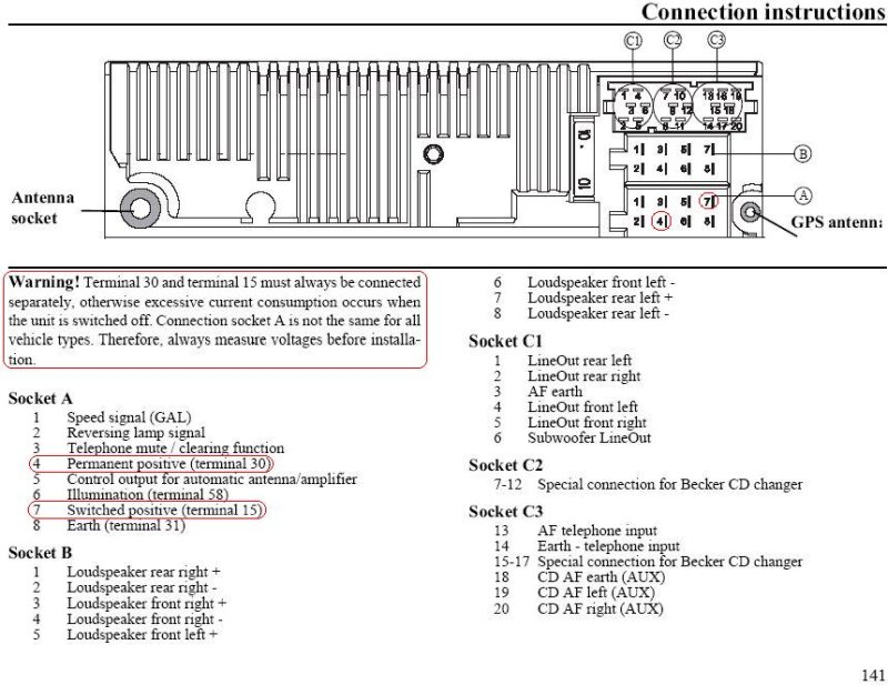
From the drawing I got from the forum I can check that the pin out of the old radio is the same as on the new radio. Power connection, Socket A, new radio:It looks that I can connect this cable direct to the new radio.
But there are some extra function I want so I install a short adapter cable between. Crossfire's are famous to take a lot of standby current, one part of that come from the radio and its power amplifier. 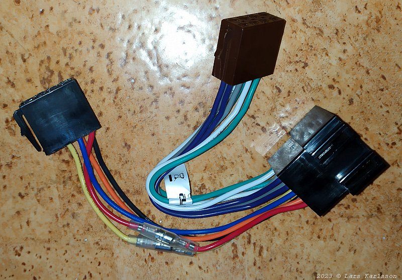
I can with this cable install a power switch, when I know that I will not use my car for more than 2 weeks I switch off the permanent power to the radio with this switch. This cable doesn't have this switch and I need to install one. What it has are two connectors that can be used to cross the connection between the yellow and red cable, permanent and switched power, +12 Volt. In some cars/radios they for some strange reason are mirrored. 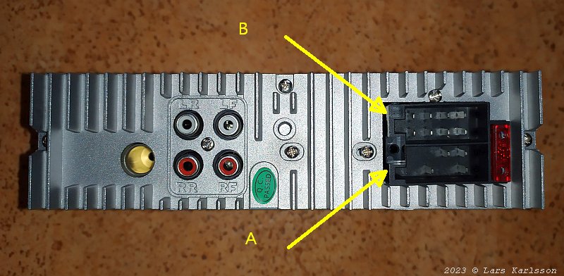
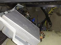
The backside of the new radio. It has the socket A for the power and socket B for the speakers. There are also low levels out put. The levels of these are too low to be compatible with the original power amplifier's input needs. Original radio, speakers:In the original radio setup they haven't connected the radio's internal amplifier direct to the speakers, the speaker outputs feed a separate power amplifier. 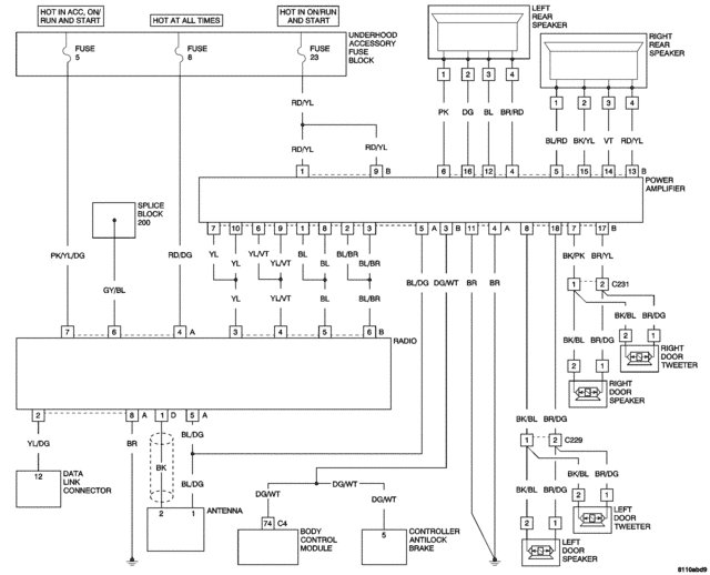
The original radio and power amplifier installation. New radio's power needs and output power:I will use the radio's internal amplifier and feed the speakers direct. In the car's manual it says that the two fuses for the radio, no 5 and 8 are 15 Amp each, the booster has another fuse, no 23 at 15 Amp. The cable area looks to be 1.5 mm2. The new radio itself has an internal 10 amp fuse. Some fast calculation shows that a total output power is limited to 85 Watt with a 10 Amp fuse. A class AB amplifier as this radio has at most 65% efficiency, the heat losses in the radio can be as high as 50 Watt, and that must be cooled away. With 4 ohm impedance speakers it could deliver maximum 22 Watt per channel with peaks of 45 Watt with not too high distortion. In reality the rear speakers will deliver a bit more and the front speaker a bit less. The original bas booster with a separate 15 Amp fuse works with 2x4 ohm impedance sub woofers and can deliver more. If I'm not satisfied with my solution it's easy to connect this booster again. ISO DIN cable extension, socket B:The distance from the radio to the power amplifier is about 1 meter and the speakers connector are down there. The connector on the radio, Socket B hold the power outlet to the four speakers. This is normally the brown socket. I just simple connect an one meter extension cable. 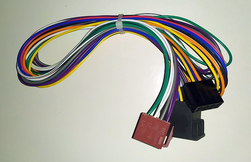
The extension cable. I only use that part with the brown Socket, the B.
The pin out for the extension cable. The speaker cable that connect to original booster:
Note: The contact on the booster that connect to all speakers are not well documented, I have to investigate the pin configuration of it. 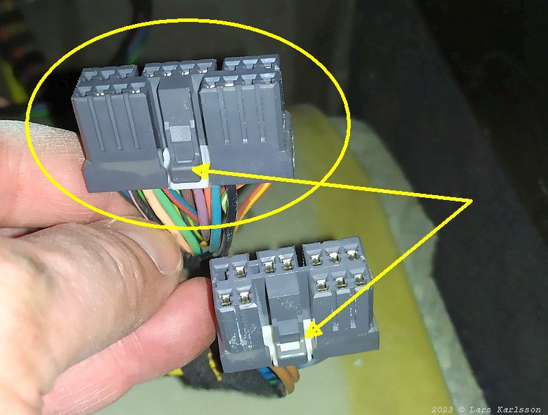
The connector B to the speakers in the car, it's a 18 pin connector, the upper one. It's to this connector the adapter cable has to fit. According to the drawing above the connector has this pin out:
* 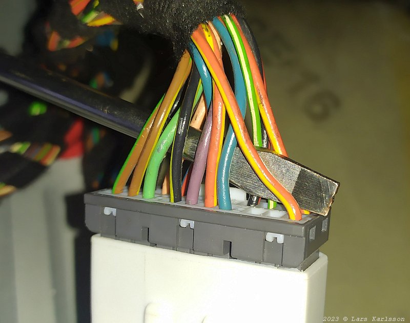
Left side of the 18 pin contact with its cables, colors are easy to see. 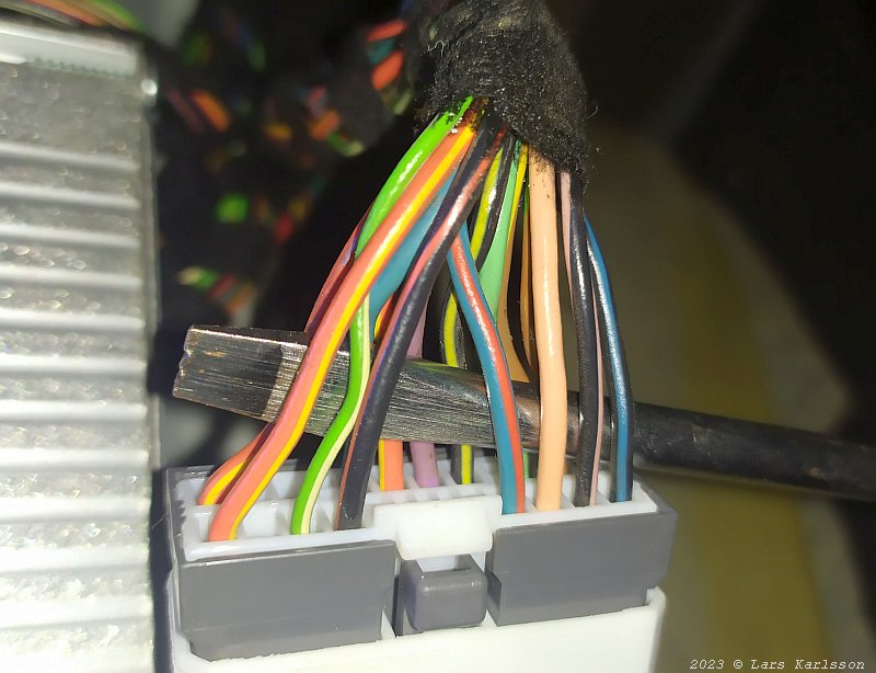
Right side of the contact. 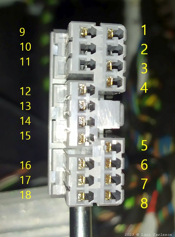
From this I can make a pin map over the connector, this is the contact on the speaker cable. 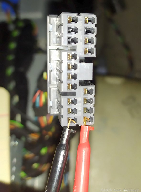
I must also test that it's correct in the drawing above where the speakers are connected, otherwise something can be destroyed if it doesn't match.
All look to match the above drawing.
I also measured the speaker's DC resistance including the cables connected to them:
Note: Speaker and others layout:
Speaker connector seen from the socket side, same as the photo above. The rear speakers are dual coils, no 1 and 2 belongs to first coil and no 3 and 4 belong to the second coil. Connecting the ISO DIN B contact to the car's 18 pin speaker contact:There are no adapters to buy for this, I have to make one by my self. My idea is to use an adapter made for the Ssang Yong car that looks to have correct connector at one end of its adapter cable. this one: adapter cable 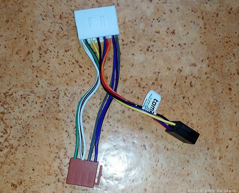
The white 18 pin connector doesn't have any brand or pin number which make this more difficult. I can see that the speaker cables from ISO DIN B connector connects to the pins at the edges of the 18 pin connector. 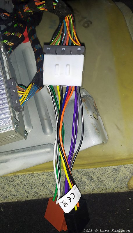
The adapters 18 pin connector fits to the car's 18 pin speaker cable's socket, the day is saved ! 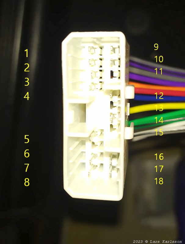
The 18 pin connector's pin out, mirrored relative the one in the car when looking to it from this side. Rewiring the ISO DIN 8 pin to Car's 18 pin adapter cable:This is how the adapter pins are connected, the ISO DIN A socket will not be used, but its cables maybe:
Almost totally wrong ! The only one that's correct is the Left Door speaker, all other are wrong connected and will cause shortcuts and more. This is how I want the wiring to be between the two contacts: Please note: This is in an early stage, maybe not correct !
Maybe I can make this adapter cable from the one above. But there are problems, not all cables are there. The socket has 18 pins but only 13 has cables attached. I only need 12 but at different pins, I have to take out some pins and move them. A little nightmare before it's done.
Note: I made a special solution for the coil 2 of the sub woofers. I used the ISO DIN A cable for them. Now in the beginning I don't use them. In the future if I replace the sub woofers with something else with single coil, then I can connect this cables in parallel with cable B. A5 to B1, A6 to B2, A7 to B7, A8 to B8. If I do it already now the impedance will be only 2 ohm and my radio can't handle that low impedance. With this also the cable area will be twice, from 0.75mm2 to 1.5mm2. Contact A4 is a spare cable and not used. Never ever connect the cable A at the radio end to something, it will be a catastrophe ! This is a special layout of the pins. Move the cables in the adapter cable: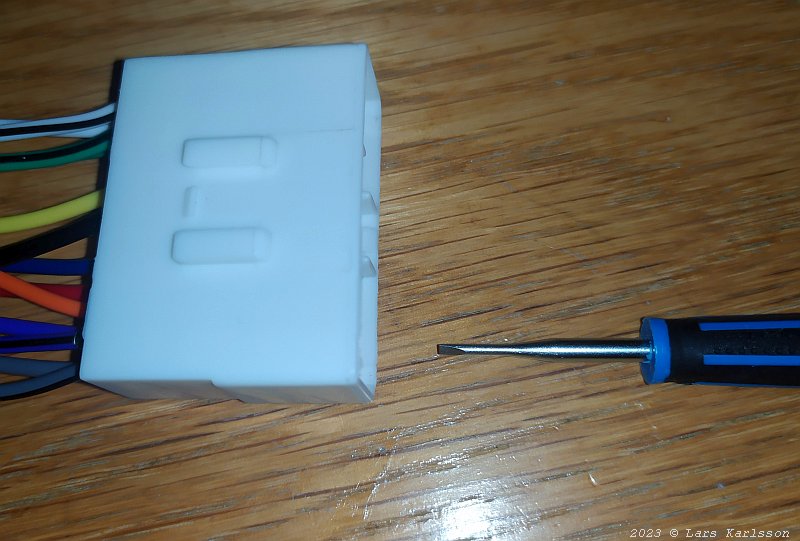
To remove the pins from the socket a special toll is needed, if you don't have that you can use a small screw driver like this. 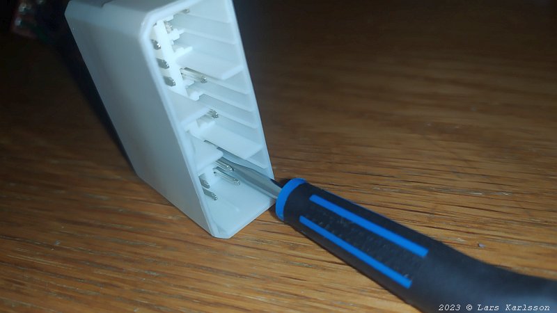
Insert the screwdriver gently on top of the pin, lift the plastic hook and gentle pull out the cable from the other side. Sometimes it release easier if you first push in the cable and then pull it out. Be careful, it's plastic. 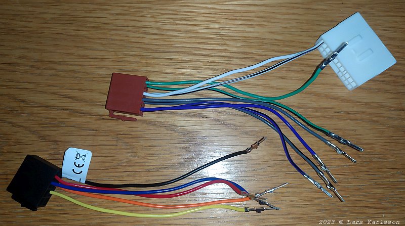
Only the white cables left, the only that was connect to correct pin. It was relative easy to remove the pins and its cables. 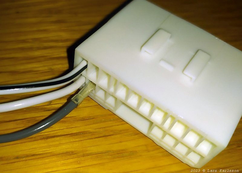
Insert the cables again but now at the places you want them. Be careful to orient the pin in correct angle. 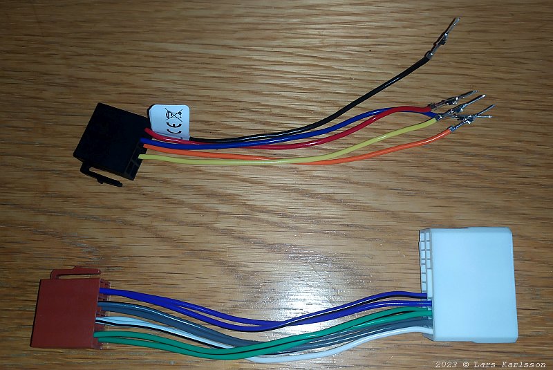
Still only the ISO DIN B cable connected to the 18 pin connector. 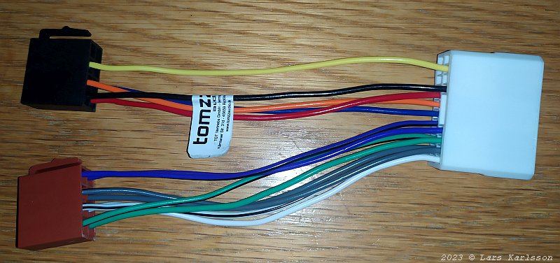
And now is the ISO DIN A connector in place. Note this A cable is very special for this and never connect it to somewhere else ! It will use it later in the other end of the extension cable to connect the sub woofer's coil 2 in parallel with coil 1. The impedance will then be only 2 ohm which most radios can't handle. But if the sub woofers is replaced with something more modern with a single 4 ohm coil the cable areas is twice with this. I will come back about this if I replace the sub woofers. Sub woofers connection alternatives:The two sub woofers with its dual coils are problematic. At Crossfire forum I read that they maybe has 4 ohm impedance.
Alternative 1:
Alternative 2:
Alternative 3:
Alternative 4:
Alternative 5:
|
|||||||||||||||||||||||||||||||||||||||||||||||||||||||||||||||||||||||||||||||||||||||||||||||||||||||||||||||||||||||||||||||||||||||||||||||||||||||||||||||||||||||||||||||||||||||||||||||||||||||||||||||||||||||||||||||||||||||||||||||||||||||||||||||||||||||||||||||||||||||||||||||||||||||||||||||||||||||||||||||||||||||||||||||||||||||||||||||||||||||||||||||||||||||||||||||||||||||||||||||||||||||||||||||||||||||||||||||||||||||||||||||||||||||||||||||||||||||||||||||||||||||||||||||||||||||||||||||||||||||||||||||||||||||||||||||||||||||||||||||||||||||||||||||||||||||||||||||||||||||||||||||||||||||||||||||||||||||||||||||||||||||||||||||||||||||||||||||||||||||||||||||||||||||||||||||||||||||||||||||||||||||||||||||||||||||||||||||||||||||||||||||||||||||||||||||||||||||||||||||||||||||||||||||||||||||
|