|
Advertisement / Annons: |
Chrysler Crossfire
|
|
2, DIY Toe-in angle meterIdeas how to built a Toe-in angle meter that doesn't cost a lot of money and is easy to use:To make it easier to measure the Toe-in I try to make a tool that I can use to measure it. It can't be too difficult when I have a 3D-priner and can do the needed CAD designs. 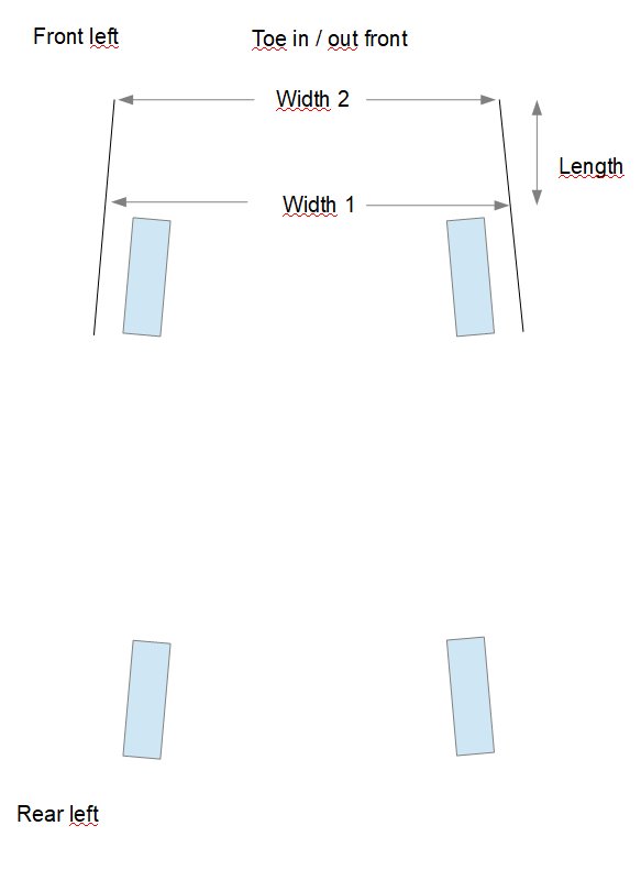
The idea of toe in measurement. DIY Toe-in angle meter:I think almost all professional wheel angles instrument use lasers and mirrors today. High precision and expensive instrument that measure all wheel angles. I only need to measure the Toe-in angle and that make it a lot easier. Here is a sketch how I thinking with a standard method to measure toe in angles. 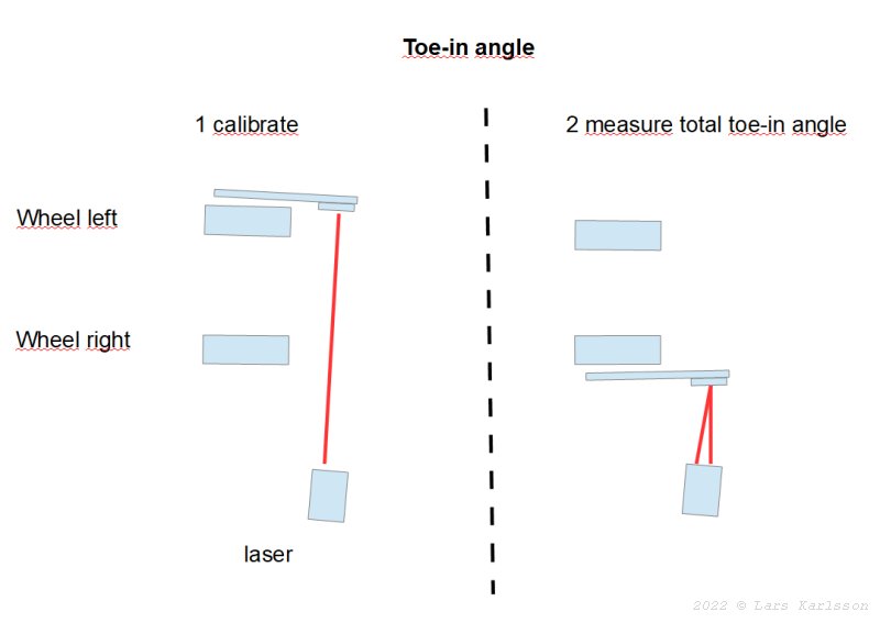
Measure
1: Later when I did this I started with the wheel that was closets to the Laser. A warning about Laser which I'm sure you already know, don't look into the Laser, it can hurt your eye. With a paper scale at the laser stand with the angles I can read it direct without calculations. The laser must stand at the same distance from the right wheel all time to get this to work. Longer distance get higher precision, I choose 2.1 meter to the left wheel. 3D-CAD of needed devices: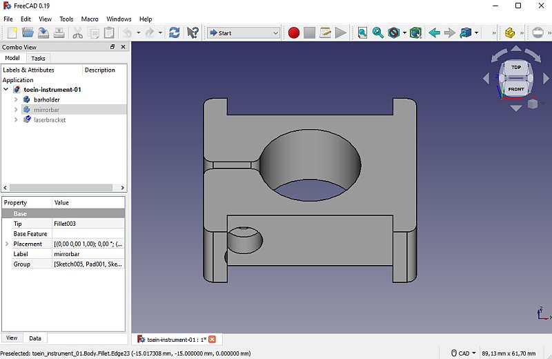
With FreeCAD I design two brackets for the tube that hold the mirror. These two points line up the tube with the wheel. A screw clamp around the tube to not let it rotate. 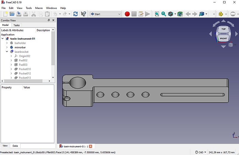
At the other end of the tube is the mirror holder. It must go down under the car so the laser beam has a free passage. I made it adjustable, the long slit. It could be a bit longer but my 3D-Printer can't print longer details then 230 mm. I plane for a mirror size of 100 mm, square or round. 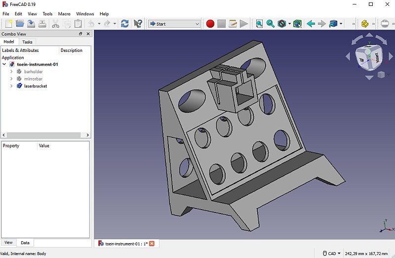
The laser pointer bracket. In the lower rectangular pocket I put a angle scale, something about +/- 1 degrees, the range depends of how far away the laser bracket is from the wheel. 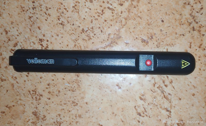
This old laser pointer was something I had in my boxes, now I got some use of it. 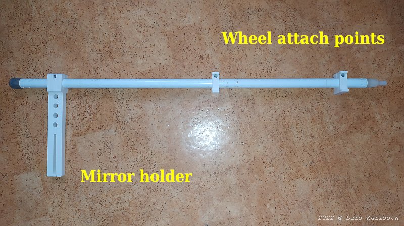
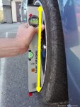
I took the tube from some scrapped cleaning equipment, it has a diameter of 22 mm. I must also design something that clamp it to the wheel. 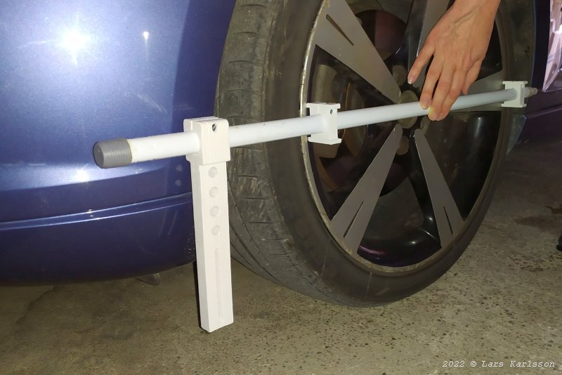
I will attach it like this to the wheels rim when I do the measurement. Mirror: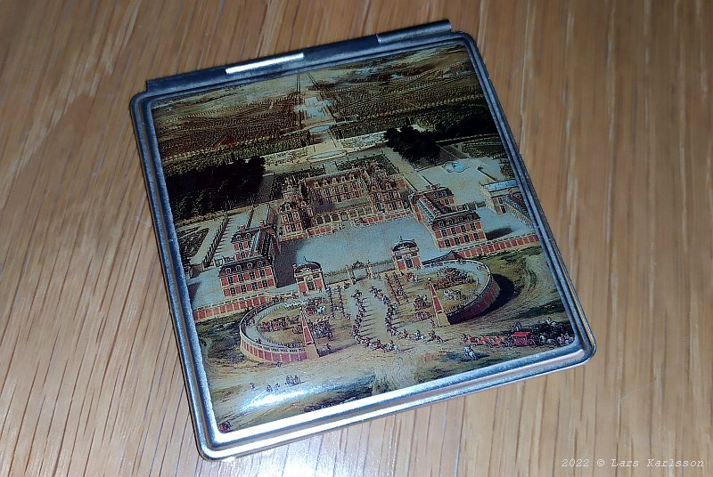
My mother in law had an old present gift in her boxes. She offered it to me for my repair of the car. 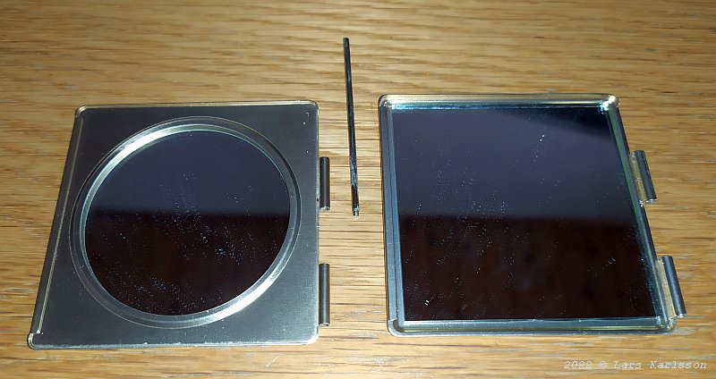
It has two mirrors, I use the square mirror to the right. To take it apart I need to remove the pin that hold the two halves together. 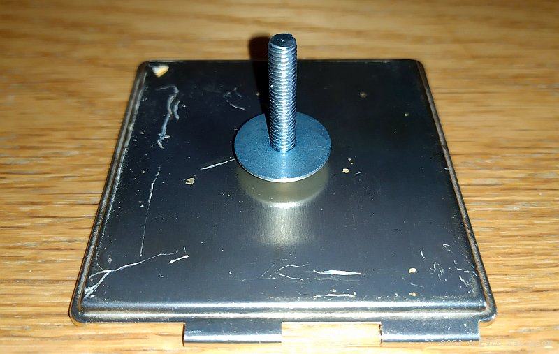
In some way I must attach it to the instrument and its mirror holder. I glued a screw on the backside of the mirror. 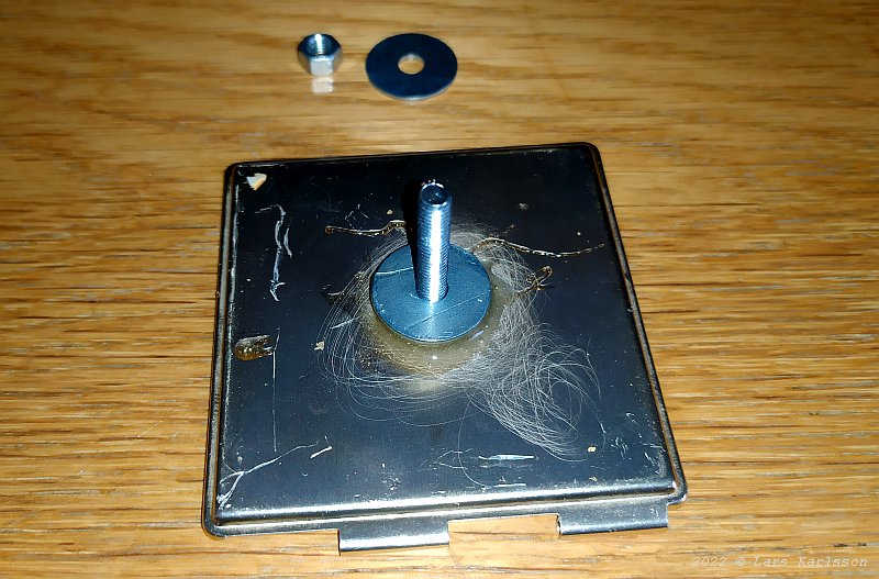
The nut and washer in the background I use to lock it to the mirror holder. 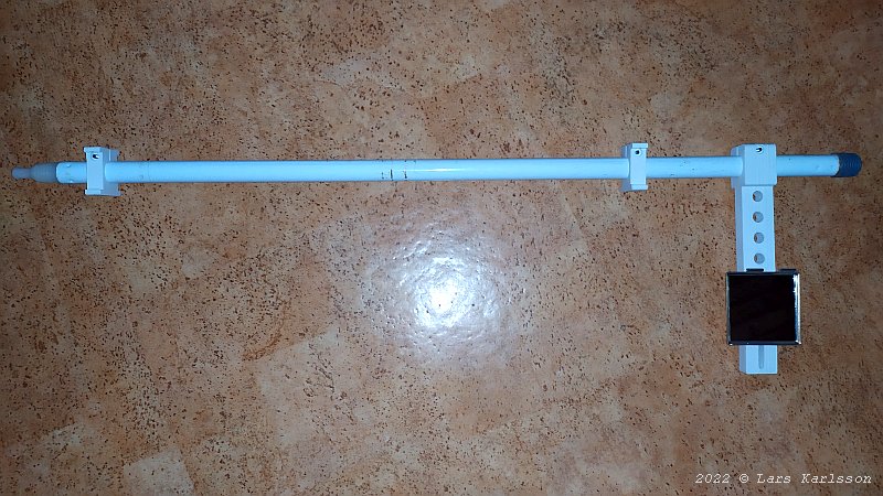
With the mirror mounted on the mirror holder arm it looks like this. 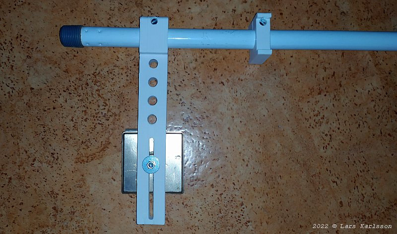
From the backside with the nut and washer that hold it in place. I can move the mirror up and down to clear the car's protruding parts below the chassi. 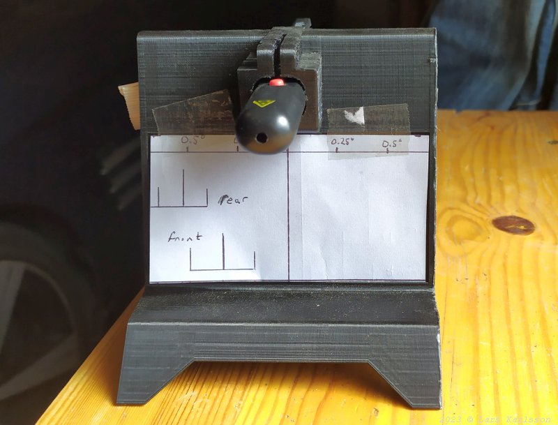
The 3D printed bracket that hold the laser pointer and plotted an angle scale. The range is about +/- 0.7 degrees. I have added markers where the limits is for the front and rear Toe-in.
|
|