


 English

|
Advertisement / Annons: |
My astronomy project:
|
Contents:
Related projects:
Note: |
7, Installing hardware in mount:Now when it isn't that could outdoors I plan to install the new hardware driver into the mount. Old original driver board: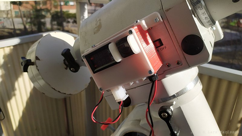
Behind my power splitter and the lid is the original hardware driver board of the mount is placed. 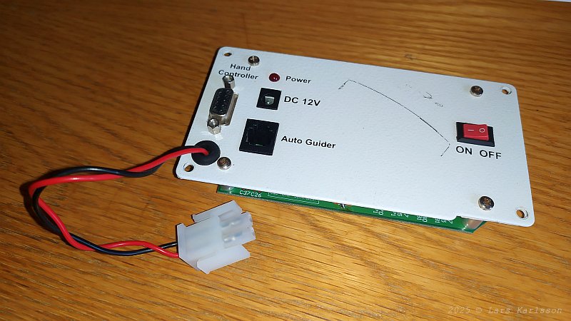
This is how the old hardware driver looks like. The cable is something extra that I have installed to get rid of the stupid original power inlet socket. It's connected in parallel with the original socket. 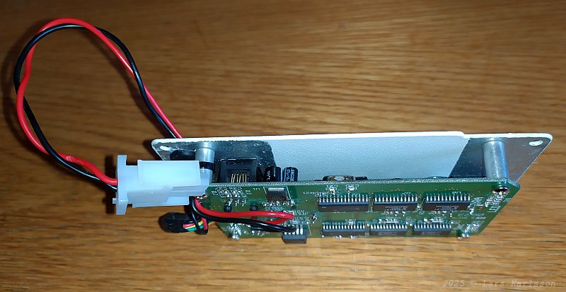
The circuit board of the driver. Now it's for sale, no use of it anymore. Installing the new driver board: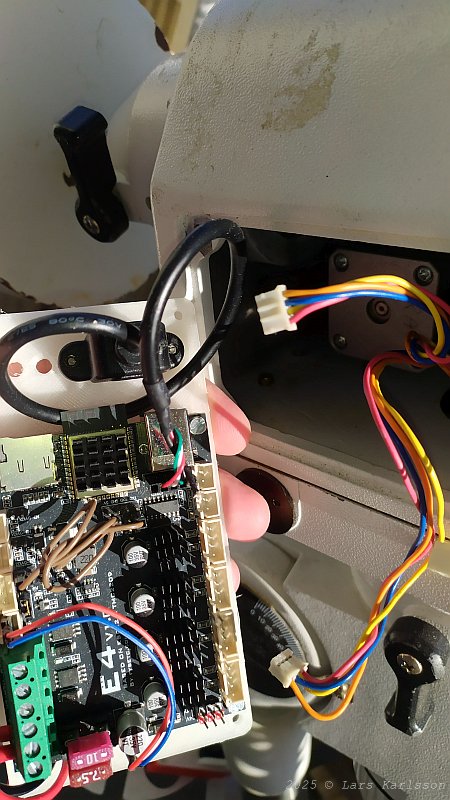
The new FYSETC E4 driver, the cables sticking out from the mount is for the stepper motors. The connectors are of a different standard and doesn't fit the circuit board. 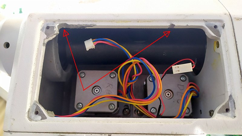
Even if the new FYSETC board is very compact it have some problem to fit in this space. The space is a bit narrow and I had to grind out a bigger opening. The Black/Red cable is for the LED in the polar scope, I don't use it. Cable adapters: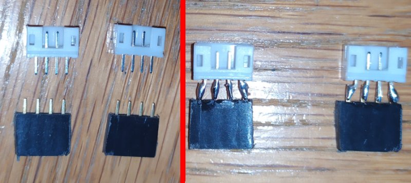
Adapter connectors for the stepper motors. The test stepper motor I used had a DC resistance of 2.4 Ohm, the EQ6 stepper motors has a resistance of 5.2 Ohm. The FYSETC E4 board has regulation of the current and adapt it to this. 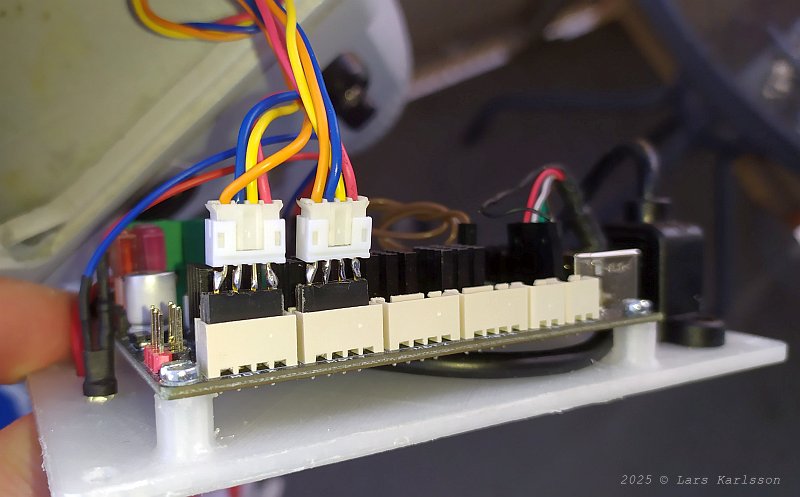
There is space behind to let the adapters fit inside the mount. To the left RA motor cable, to right the DEC motor cable. A warning about to have it like this, if one cable jumps out when the power is on it can destroy the controller board. Power up: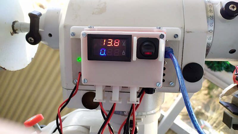
Power it up, first I thought it doesn't work, but when putting the ear to the mount I can hear the stepper motors spin inside. So much quieter than the original driver. The rotation direction was correct too. I only have some issues with the parking position. The rest current is about 0.65 Ampere, same as before. Next thing to do is to install a temperature sensor and a humid sensor. It's already there in the software. |
|
|