|
Advertisement / Annons: |
My astronomy project:
|
Content:
Repair the friction coupling: Related projects:
Note: |
2: Disassembling the focuserSo now I have to disassembly part of the the telescope to reach the focuser. First I have to remove the driver box (see photo from page 1) to the focus motor and the USB Hub. I's just mounted with one screw so it's easy to remove, must be very careful to not rip off the cables from the stepper motor.
Note: If you want to know more about how I built it you have the information here:
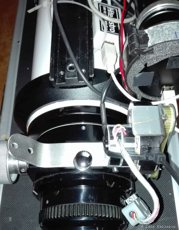
To hold the stepper motor in place I have built a bracket, that one too have to be removed. Very narrow space to access the screws that hold the motor / gearbox. Have to be very careful with the motor and gearbox, the motor is only glued together with the gearbox, it has already came loose once. Here you see the cable clearly to the stepper motor and the timing belt to the right. After I have loosen the screws that hold the stepper motor I can take away the timing belt. 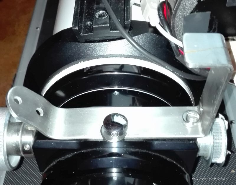
One of the screws that hold the bracket is also where I adjust the tension of the tooth belt, the screw to the right. I adjust it with shims in the form of washers I put in between. The center knob is where you look the focus, I don't use that function, have it as a holder for the focus motor instead. I didn't want to drill any new holes to hold the motor focus, that's why it looks like this. 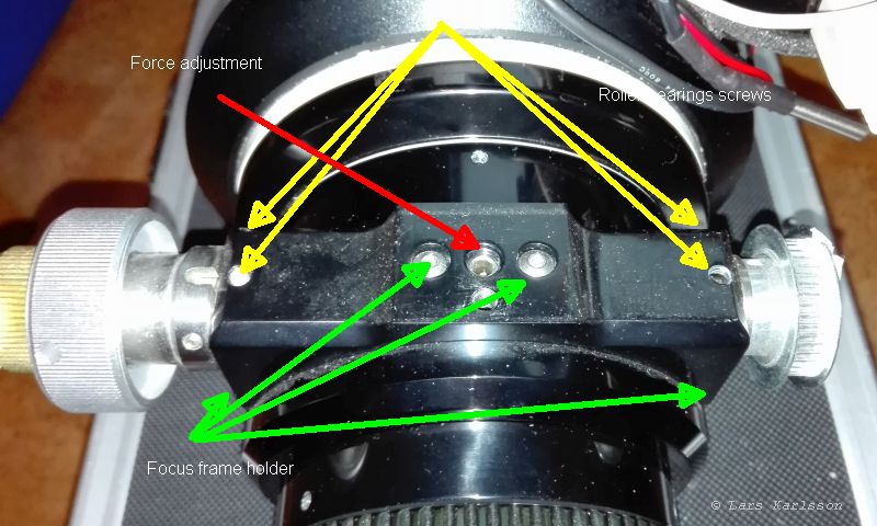
With the bracket removed we can now see the chassis that holds the mechanism to the focuser. Red arrow, this is the screw to adjust the force on the friction drive. Yellow arrows, screws that hold the two roller bearings, four of them. Green arrows, here are the screws that hold the chassis to the focuser, six of them. 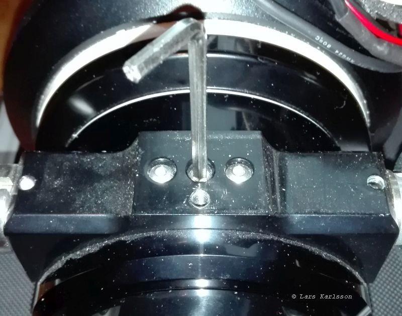
Loosen the adjuster screw, I take it all the way out, but then I can't install it again if I not remove everything completely, but that is what I'm going to do here. The screw most to the right is also a tension screw for the focuser. 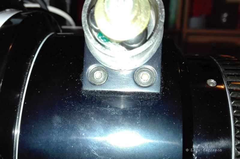
After removing the focus knob I can reach the screws that holds the focus chassis, there are two more hex screws on the other side too which I reach after removing the pulley. 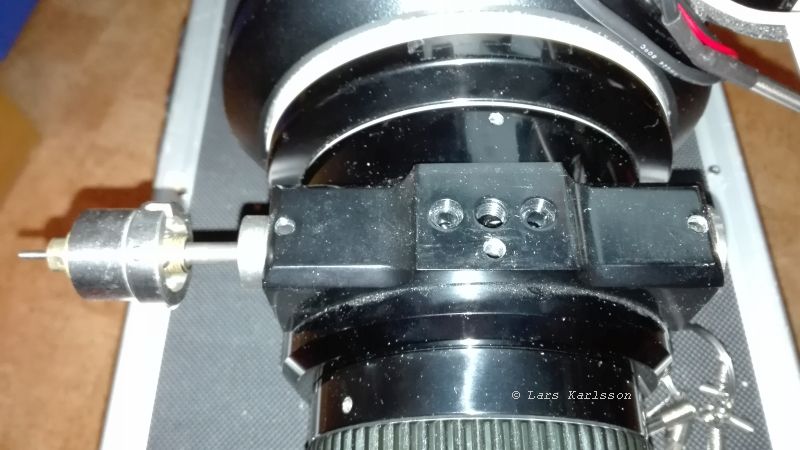
After I removed the pulley on the right side, I pull the axis out to the left. It's easier if I rotate the axis when if I pull it sideways. What you see to the left is the 1:10 gearbox, also of friction type. It's not possible to lift the focus chassis away until the axis has been removed. Don't forget to loosen the screw to the right ! After this I can lift the focus chassis away. Pull out the focuser draw tube. One must be careful, it's high precision mechanics, I don't want to scratch the surfaces. Don't either touch the black surfaces inside and leave grease finger prints on them, it will lower the contrast.
|
|