|
Advertisement / Annons: |
My astronomy project:
|
Content:
Note: |
4: Investigating vignetting problemNow the telescope and adapters are ready for test and I can start picking up the first astronomy photos. I already in the first test noticed that it had some vignetting problem and I will now investigate what caused that. The image in the example had just been dark subtracted and color channels where scaled, red 150% and blue 190% so they normalize at the same level. There is a stack of 53 x 30 seconds at ISO 800. If the signal is about 200 ADU in the center and one reads of 140 at the edge, the signal is thus reduced by 30% due to vignetting. 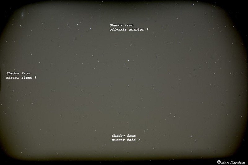
Here it's clear that the system vignetting heavily in places where it should not be a problem.
Note that vignetting is not rotationally symmetrical but rectangular in parts,
the two circular vignettings comes from limitations in the adapters.
The rectangular vignetting can not be interpreted in any other way than the camera body is too narrow. Have written about it
before but now I have measured it so it can be better seen what happens.
With a worse field flattener in 2" mount this had not been seen so clearly
then instead the field flattener inherent vignetting had dominated and it had seen more like a circle.
NOTE: There is a dark frame along the edge because it is photographed with dithering, but it is barely visible on this scale.
Such large vignetting like this is very difficult to handle with flat field calibration.
You have to crop a big portion to get rid of it.
You may have read in my thread of thoughts about the Sony A7 series mirror less camera.
Canon has a back focus of 44mm Sony A7R II has only 18mm,
read here: Let us study it in more detail: 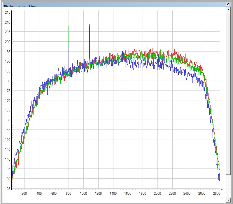
Here is an line graph done from the top down to bottom (vertical). The sensor is 24mm in height and the signal strength of the edges drops dramatically. It is the camera's mirror in the up position that obscures the light cone. The two vertical lines are the stars I happened to cross when I drew the line. The signal drops to 140 units here at the edges, should instead remained at 160-170 with this field flattener. Extend only the line that goes to the edge without the sharp bend that becomes close to the edge. One thing that puzzled me at first is why the signal is higher on the right side and not symmetrical, furthermore distinguishes between the different wavelengths. But the side is higher on the downhill. Interprets it as a gradient starry sky and downside has more light pollution. Se also the sharp bent to the right, it is the top of the camera body where we have the mirror. 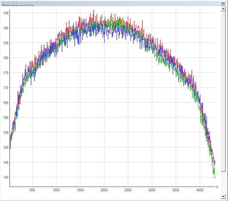
Here are the corresponding line graph horizontally. Apparently, the signal is much higher here at the equivalent distance of 24 mm or +/- 12 mm (+/- 1400 pixels) from the center. Compare the level of the corresponding distance in height you can see that they have the level of 170 units and not 140 as it was in the previous line graph. This is the level you have from the corrector itself, the narrow width of the camera body and small openings in adapters limiting the signal farther to the edges. Very irritating to loosing signal due to this. 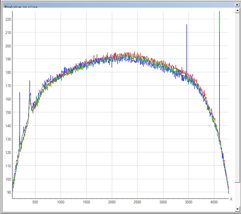
Here it is instead the diagonal that the signal is measured along. The second peak from the left side is a galaxy. Here one can see that the signal should be around 160 units at the edges. Thus, the center 190, 12 mm out of 175, 18 mm out of 170 and edges 160 units, very good values and thus little vignetting. So what to do with the camera body restrictions on the cone of light into the sensor? This was a problem I had not taken into account, have actually never heard it mentioned, but now when studying camera body closer it is so obvious. 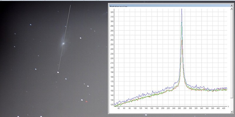
I was aiming at the M106 galaxy, have not really had time to check where it ended up in the picture. Perhaps it is that galaxy we see in the upper left corner. Also I have done a line graph to show how the Galaxy stands out from the background. Galaxy core has signal strength about 300 and the disc is around 150, from this subtract the background so the disk might have only one signal contribution of 5 to 10 units. The background signal 150 has an internal noise of about 12 units, greater than galaxy disc. Therefore, it's not good to shoot astronomy photos from my balcony but far out of town so this background signal and noise disappears. Alternatively, the narrow-band techniques, on nebula. 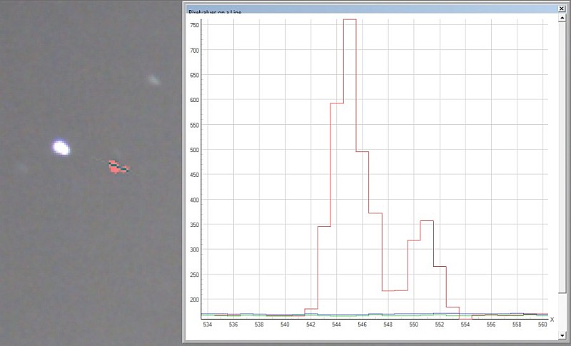
Finally, I have detailed studied how the dithering technique has worked in the hot pixels (red here). As you can see dithering spread out over several pixels at a weaker level as a consequence, note this is an extreme case with a hot pixel of perhaps 100%. However, there have been two groups, the left and right. Something has probably gone wrong with the automatic stacking process out so that reference star had been shifted to some other. Explain the part of the elongated stars, but still depends mostly on the optics, the distance between flat field corrector and the sensor is wrong, and yes, with some fine adjustment it is possible to get it better.
|
|