|
Advertisement / Annons: |
Project:
|
Content: |
2: 3D CAD design LED bracketDesigning the LED stripe bracket and diffuser. Another setup of the jar:With the positive results after I rearranged the LED stripe I continue to develop my flat box which is more round nowadays. 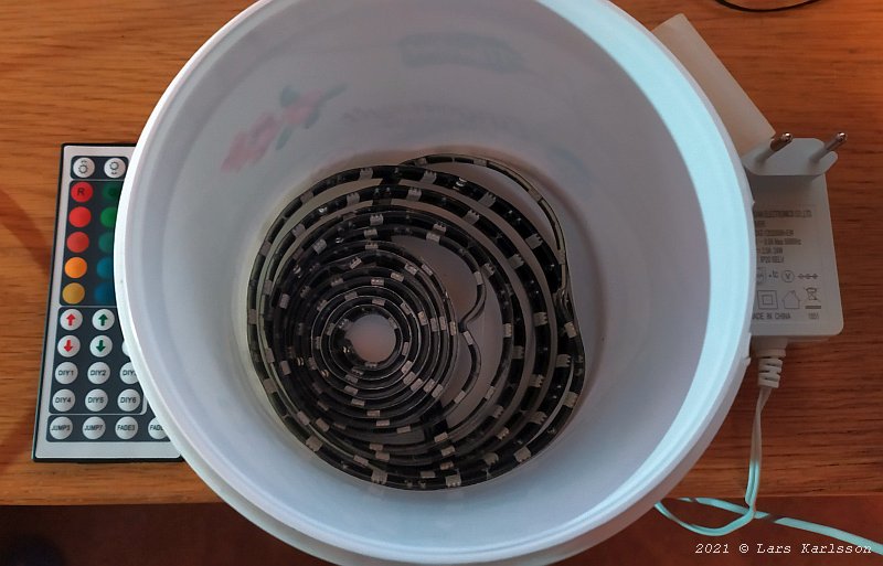
What I did was to move the LED stripe from outside of the can to inside. Formed it as a spiral and placed at the bottom. It's a mess here but before it was a nice spiral. The LEDs has high power and could only be used like this for a short moment to not overheat. Above this I had placed a diffuser to get a more even light. It didn't work much better, it's time to do some more specialized bracket and diffuser but at least I got some ideas how to develop it. 3D CAD: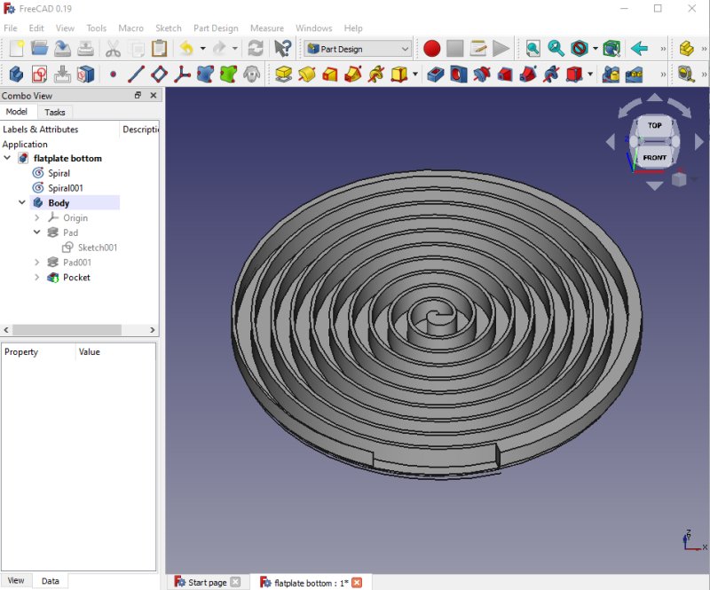
With the experience I got from this I have designed a new LED stripe bracket. It's open on the backside to let the heat out. It now has a diameter of 212 mm. This let me use it to my 5" APO refractor and the smaller lenses. The bottom of it is facing to the lens and act as the first diffuser at the same time. This is on the limit of what size my 3D-printer can handle. With this I learned how to do CAD spiral pattern, more to read here if you find it interesting: 3D-Printing flat LED stripe holder. One problem, it will take 17 hours to print this bracket. 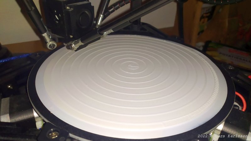
Now this long time 3D-Printing has started. I got up 3 am in the morning and started the 3D-Printer. This is the first time since I did some fix about the nozzle temperature regulation. It wasn't stable enough earlier and the 3D-Printer got in safety mode. After 5 hours the bottom plate is finished and it has started to print the spiral pattern, no failure yet. 12 hours left. 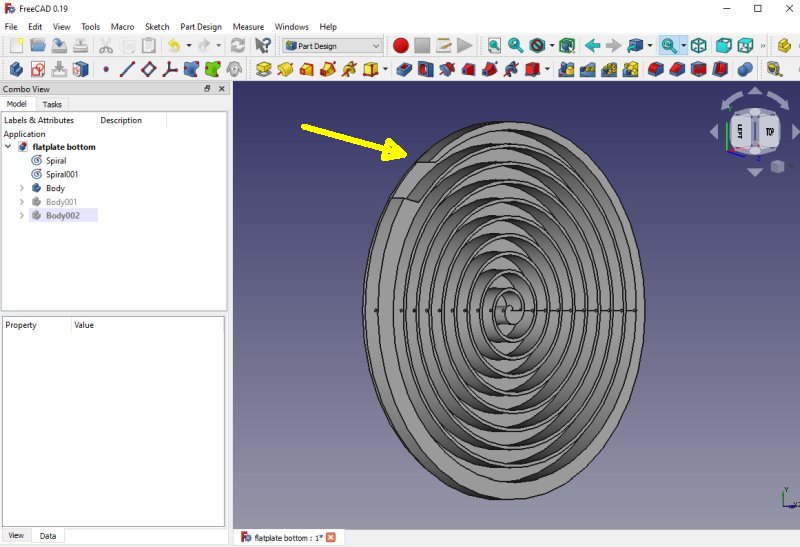
I could already see when it printing that there was a problem. The edge is too thin and it didn't print that part well. While the 3D-Printer still working I updated the drawing with thicker walls at the rim. 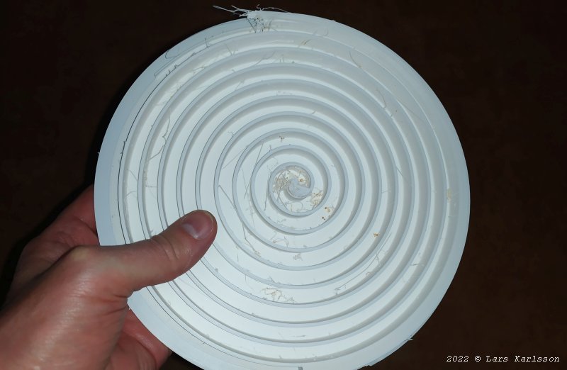
It took little bit more time, 18 hours. Direct out from the 3D-Printer, looks good. 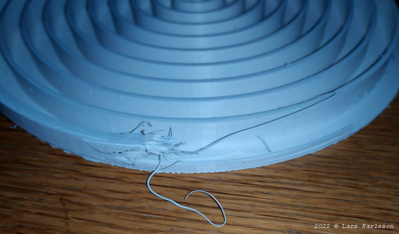
This is how the failed edge looks. Too thin walls, when it got less than 2 mm thick the 3D-printer got in trouble. 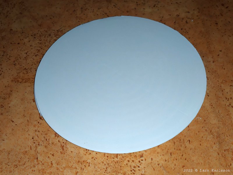
The backside, this is the side which will be towards the camera, it acts at the same time as the first diffuser. 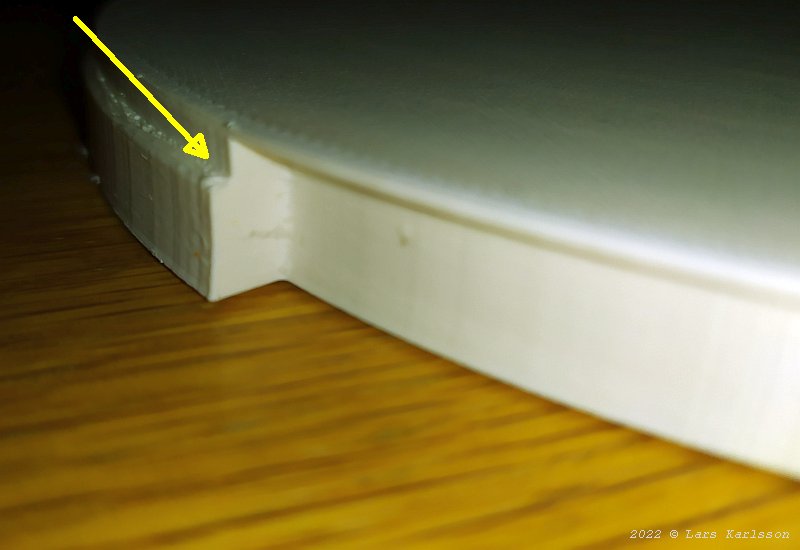
This edge will connect to next part of the flat box, the middle 2nd diffuser cylinder. 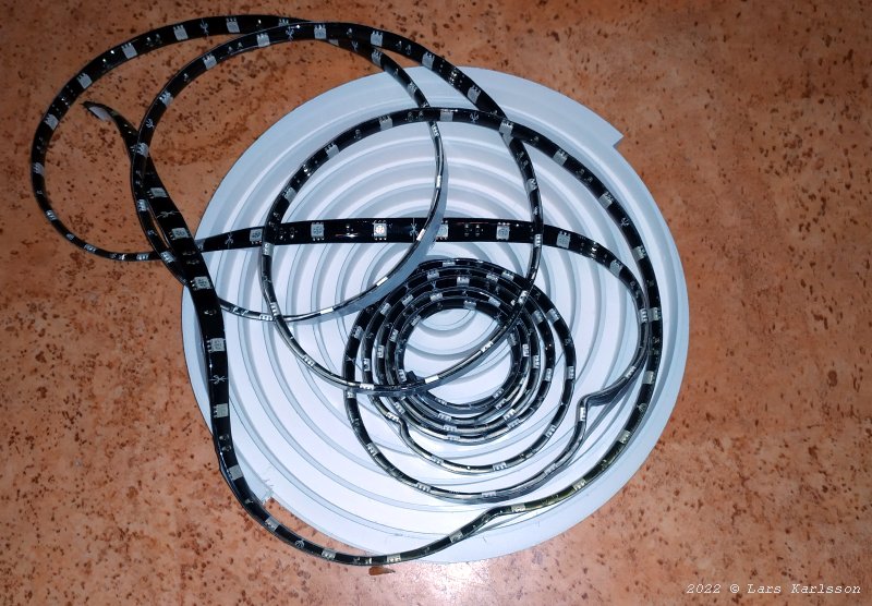
Now, will the LED stripe fits in this spiral pattern, it looks a bit too long, have I miss calculated it ? 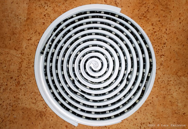
No, perfect, the power cable fits inside here also and connect to the LED stripe. 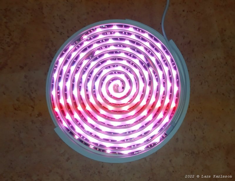
First light, this is the side that is open to the air to get maximum cooling. The LED stripe is self-adhesive, I haven't take away the protection film yet, after I have done that it will fit better. 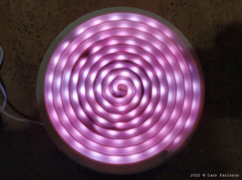
The other side which is towards the camera. The dark spots is where the stripe doesn't attach correctly because I haven't removed the protection film yet. One more diffuser will sit about 40 mm above this surface and if it's needed I can put in one more just in front of the camera.
|
|